
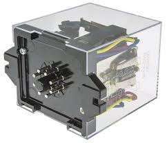
Rơ le tích hợp G6B-4BND DC24 Omron
Compact Terminal Relay with 4 Independent Outputs
• Equipped with four G6B Mini-relays that are compact, highly sensitive, and highly resistant to dielectric surges, and that can switch 5 amps of power.
• Sealed plastic construction used for relays.
• Easy wiring with separated input/output terminals.
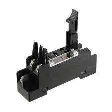
• Special P6B Mounting Socket used to facilitate maintenance (except for high-reliability models).
• UL and CSA certification for standard models (except for high-reliability models). VDE certification for G6B-4BND/47BND/48BND for 12/24 VDC.
• DIN Track mounting, and screw mounting models are available.
• SSR-equipped G3S4 models are also available.
Ratings
Coil Ratings (per G6B Relay)
| Rated voltage | 5 VDC | 12 VDC | 24 VDC |
|---|---|---|---|
| Rated current | 35.5 mA (43.4) | 19.1 mA | 10.7 mA (10.3) |
| Coil resistance | 125 Ω | 720 Ω | 2,880 Ω |
| Must operate voltage | 80% max. of rated voltage | ||
| Must release voltage | 10% min. of rated voltage | ||
| Max. voltage | 130% of rated voltage | ||
| Power consumption | Approx. 200 mW | ||
Note: 1. Rated current and coil resistance were measured at a coil temperature of 23°C with a tolerance of ±10%.
2. Operating characteristics were measured at a coil temperature of 23°C.
3. The maximum allowable voltage is the maximum value of the allowable voltage range for the relay coil operating
power supply. There is no continuous allowance.
4. Diodes to absorb coil surge are equivalent to S5688J (reverse voltage resistance: 600 V; forward current: 1 A).
5. The values in parentheses are for the G6B-4FB1ND and G6B-4FPND.
6. The rated current includes the LED current.
Contact Ratings
| Classification | G6B-4BND (standard), G6B-47BND (long-life) | G6B-48BND (high-reliability) | ||
|---|---|---|---|---|
| Load | Resistive load (cosφ = 1) |
Inductive load (cosφ = 0.4, L/R = 7 ms) |
Resistive load (cosφ = 1) |
Inductive load (cosφ = 0.4, L/R = 7 ms) |
| Rated load | 5 A at 250 VAC, 5 A at 30 VDC |
2 A at 250 VAC, 2 A at 30 VDC |
2 A at 250 VAC, 2 A at 30 VDC |
0.5 A at 250 VAC, 0.5 A at 30 VDC |
| Rated carry current | 5 A | 2 A | ||
| Max. switching voltage | 380 VAC, 125 VDC | |||
| Max. switching current | 5 A | 2 A | ||
| Max. switching power | 1,250 VA, 150 W | 500 VA, 60 W | 500 VA, 60 W | 125 VA, 15 W |
| Error rate (reference value) (see note) |
10 mA at 5 VDC | 1 mA at 1 VDC | ||
Note: This value fulfills the P reference value of opening/closing at a rate of 120 times per min (ambient operating
environment and determination criteria according to JIS C5442).
environment and determination criteria according to JIS C5442).
Characteristics
| Contact resistance (see note 2) |
100 mΩ max. |
|---|---|
| Operate time | 10 ms max. (approx. 3 ms) |
| Release time | 15 ms max. (approx. 4 ms) |
| Insulation resistance | 1,000 MΩ min. (at 500 VDC) |
| Dielectric strength | 2,000 VAC, 50/60 Hz for 1 min between coil and contacts 2,000 VAC, 50/60 Hz for 1 min between contacts of different polarity 1,000 VAC, 50/60 Hz for 1 min between contacts of same polarity 250 VAC, 50/60 Hz for 1 min between coils of different polarity |
| Vibration resistance | Destruction: 10 to 55 to 10 Hz, 0.75-mm single amplitude (1.5-mm double amplitude) Malfunction: 10 to 55 to 10 Hz, 0.75-mm single amplitude (1.5-mm double amplitude) |
| Shock resistance | Destruction: 1,000 m/s2 (approx. 100G) Malfunction: 100 m/s2 (approx. 10G) |
| Endurance | Mechanical: 50,000,000 operations min. (at 18,000 operations/hr) Electrical: 100,000 operations min. (at 1,800 operations/hr, rated load) 500,000 operations min. for long-life at 2 A 100,000 operations min for long-life at 5 A |
| Ambient temperature | Operating: -25°C to 55°C (with no icing or condensation) Storage: -25°C to 55°C (with no icing or condensation) |
| Ambient humidity | Operating: 35% to 85% |
| Weight | Approx. 75 g |
Note: 1. The above values are initial values.
2. Measurement condition: 1 A at 5 VDC
2. Measurement condition: 1 A at 5 VDC


Reviews
There are no reviews yet.