


Bộ lập trình PLC Panasonic AFPX0L40R
PLC đa năng & kinh tế( mới)

Đặc trưng
Rất nhiều điểm I/O -150 điểm tối đa. [L40□ / L60□]
Nếu khách hàng không thể dự đoán số lượng điểm I/O mà máy móc và thiết bị của mình cần trong tương lai, họ sẽ cảm thấy do dự và khó chịu. Tuy nhiên, số I/O của FP-X0 có thể đạt tối đa 150 điểm. bằng cách sử dụng thiết bị mở rộng FP-X. Do đó, sự khó chịu và do dự của khách hàng có thể được loại bỏ.
(L14R và L30R không có chức năng mở rộng nên không thể mở rộng.)
• Số khối mở rộng tối đa lên tới 3 khối.
![Plenty of I/O points -150 points max. [L40□ / L60□]](https://www3.panasonic.biz/ac/ae/fasys/plc/plc/fp-x0/images/pic02.jpg "Bộ lập trình PLC Panasonic AFPX0L40R 7")
![Plenty of I/O points -150 points max. [L40□ / L60□]](https://www3.panasonic.biz/ac/ae/fasys/plc/plc/fp-x0/images/pic03.jpg "Bộ lập trình PLC Panasonic AFPX0L40R 8")
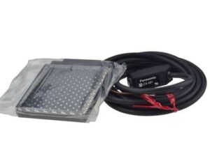
Cáp giữa các mô đun có thể được uốn cong để
lắp đặt song song, do đó tiết kiệm không gian lắp đặt.
Mở rộng hơn nữa và nhiều chức năng hơn đạt được bằng cách sử dụng đơn vị mở rộng FP0R hiện có một cách dễ dàng [L40□ / L60□]
Số lượng đơn vị mở rộng FP0R tối đa lên tới 3 sau khi các đơn vị điều khiển được trang bị bộ điều hợp( adapter).
Có thể đạt được phạm vi ứng dụng rộng hơn bằng cách sử dụng [đầu ra bóng bán dẫn], [I/O tương tự], [đầu vào cặp nhiệt điện] và [I/O LINK (mạng)].
Chỉ có thể cài đặt một bộ điều hợp mở rộng FP0 trên thiết bị điều khiển.
Ngoài ra, hai thiết bị mở rộng FP-X có thể được cài đặt sau khi bộ điều hợp được cài đặt.
(L14R và L30R không có chức năng mở rộng nên không thể mở rộng.)
![Further expansion and more functions achieved by using the existing FP0R expansion unit easily [L40□ / L60□]](https://www3.panasonic.biz/ac/ae/fasys/plc/plc/fp-x0/images/pic04.jpg "Bộ lập trình PLC Panasonic AFPX0L40R 9")
Bên cạnh cáp mở rộng được cung cấp có các loại 8 cm (3.150 in), 30 cm (11.811 in) và 80 cm (31.496 in) cũng được bán riêng.
Chúng có thể được uốn cong hoặc duỗi thẳng. (Tổng chiều dài phần mở rộng nằm trong khoảng 160 cm 62,992 in.)
![Further expansion and more functions achieved by using the existing FP0R expansion unit easily [L40□ / L60□]](https://www3.panasonic.biz/ac/ae/fasys/plc/plc/fp-x0/images/pic05.jpg "Bộ lập trình PLC Panasonic AFPX0L40R 10")
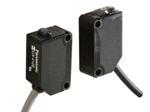
Cả hai đều là 90 mm (3,543 in) và có thể được cài đặt trong tủ.
Tốc độ xử lý siêu cao
Tốc độ siêu cao 80 ns/bước cho 0 đến 3.000 bước (lệnh ST). Tốc độ xử lý 580 ns/bước cho 3.001 bước trở lên (Chỉ dành cho L40□ và L60□).
Thân máy được trang bị đầu ra rơle và bóng bán dẫn kết hợp

Chức năng đầu ra xung / Chức năng bộ đếm tốc độ cao

Chức năng đầu ra xung của FP-X0 (1 trục cho L14R và 2 trục cho L30R / L40□ / L60□) được tích hợp trong phần thân của thiết bị điều khiển.
So với PLC trước đó phải sử dụng các thiết bị định vị tiên tiến hoặc cụ thể hoặc nhiều hơn hai thiết bị điều khiển đa trục, FP-X0 về cơ bản chỉ sử dụng một thiết bị, do đó tiết kiệm không gian và giảm chi phí.
Bộ đếm tốc độ cao 4 điểm tích hợp
4 điểm cho 1 pha hoặc 2 điểm cho 2 pha (X0 đến X3)

Áp dụng phép nội suy tuyến tính 2 trục [L40□ / L60□]
![Adopting 2-axis linear interpolation[L40□ / L60□]](https://www3.panasonic.biz/ac/ae/fasys/plc/plc/fp-x0/images/pic09.jpg "Bộ lập trình PLC Panasonic AFPX0L40R 14")
Nội suy tuyến tính 2 trục là một loại chức năng điều khiển 2 trục động cơ và làm cho cánh tay robot và đầu công cụ thực hiện chuyển động theo đường chéo đồng thời, được áp dụng trong các bộ phận gắp & lắp của xe xếp, điều khiển bàn làm việc XY và cắt tấm đế …
Thông số kĩ thuật Bộ lập trình PLC Panasonic AFPX0L40R
Spec Detail
| Item | Specifications |
|---|---|
| Product Number | AFPX0L40R |
| Part Number | AFPX0L40R |
Performance specifications
| Item | Specifications |
|---|---|
| Controllable I/O points : Control unit | DC input: 24 points Relay output: 12 points Transistor output: 4 points |
| Controllable I/O points : When using FP-X E16 expansion I/O units | 88 points max. (3 expansion units max.) |
| Controllable I/O points : When using FP-X E30 expansion I/O units | 130 points max. (3 expansion units max.) |
| Controllable I/O points : When using FP0R expansion units | 196 points max. (3 expansion units max.) |
| Programming method/Control method | Relay symbol/Cyclic operation |
| Program memory | Built-in Flash-ROM (Free of backup battery) |
| Program capacity | 8 k steps |
| No. of instruction : Basic commands | Approx. 114 kinds |
| No. of instruction : High-level commands | Approx. 230 kinds |
| Processing speed | 3 k steps: 0.08 μs/step for basic commands, 0.32 μs for high-level commands (MV commands) After 3 k steps: 0.58 μs/step for basic commands, 1.62 μs for high-level commands (MV commands) |
| Processing speed : Basic time | 0.31 to 0.35 ms or less |
| I/O refreshing + basic time | When using E16: 0.4 ms × No. of units When using E30: 0.5 ms × No. of units When using FP0 expansion adapters: 1.4 ms + the refreshing time of the FP0 expansion unit |
| Memory for processing : Relays : External input (X) | 1,760 points (Note) The actual usable points depend on the combination of the hardware. |
| Memory for processing : Relays : External output (Y) | 1,760 points (Note) The actual usable points depend on the combination of the hardware. |
| Memory for processing : Relays : Internal relay (R) | 4,096 points |
| Memory for processing : Relays : Special internal relay (R) | 224 points |
| Memory for processing : Relays : Timer・Counter (T/C) | ・1,024 points(Note) ・Timer: (1 ms, 10 ms, 100 ms, 1 s) × 32,767 ・Counter: 1 to 32,767 (Note) The points of the timer can be added as required. |
| Memory for processing : Relays : Link relay (L) | 2,048 points |
| Memory for processing : Memory area : Data register (DT) | 8,192 words |
| Memory for processing : Memory area : Special data register (DT) | 420 words |
| Memory for processing : Memory area : Link data register (LD) | 256 words |
| Memory for processing : Memory area : File registration (FL) | No |
| Memory for processing : Memory area : Index register (I) | 14 words (IO to ID) |
| Differential points | Equivalent to program capacity |
| Master control relay (MCR) | 256 points |
| Label number (JP+LOOP) | 256 points |
| No. of step programs | 1,000 (Engineering) |
| No. of subroutines | 500 |
| No. of interrupt programs | Input: 8 programs timing: 1 program |
| Sampling trace | Yes |
| Comments storage | All of the I/O comments,explanations and block comments can be saved. (Free of backup battery, 328 k bytes) |
| PLC link function | Yes |
| Constant scan | In unit of 0.5 ms: 0.5 ms to 600 ms |
| Password | Available (4 or 8 digits) |
| Upload protection | Available |
| Self-diagnosis function | Checks of the watchdog timer and the program syntax |
| Program editting during Run | Available (Capacity modified simultaneously: 512 steps) But comments can be modified during the process. |
| Downloading during Run | Available |
| High-speed counter : Body input | 1-phase, 4-channel (20 kHz max.) and 2-phase, 2-channel (20 kHz max.) (Note) The rated voltage is 24 V DC at +25 ℃+77℉. The frequency may fall according to the changes of the voltage, temperature and operating conditions. (Note) The maximum frequency may vary with the difference of the operating method. |
| Pulse output/PWM output : Body output | Pulse: 2-channel (50 kHz) or PWM: 2-channel (3.0 kHz max.) (Note) The rated voltage is 24 V DC at 25 ℃. The frequency may fall according to the changes of the voltage, temperature and operating conditions. (Note) The maximum frequency may vary with the difference of the operating method. |
| Pulse catch input/Interrupt program | 8 points (High-speed counting and interrupt input included) |
| Periodical interrupt | 0.5 ms unit: 0.5 ms to 1.5 sec., 10 ms unit: 10 ms to 30 sec. |
| Analog input | 2-channel (For inputting any of the following items in each channel) Potentiometer input ・Min. resistance value of potentiometer: 5 kΩ ・10-bit resolution (K0 to K1,000) ・Accuracy ± 1.0% F.S.+ accuracy of external reistors Thermistor input ・For inputting the resistance value of the thermistor (Min. resistance value of external thermistors + external resistance value > 2 kΩ) ・10-bit resolution (K0 to K1,023) ・Accuracy ± 1.0% F.S.+ accuracy of external thermistors Voltage input ・Absolute max. input voltage: 10 V ・10-bit resolution (K0 to K1,023) ・Accuracy ± 2.5% F.S. (F.S. = 10 V) |
| Calendar/clock | Yes |
| Flash ROM backup : Backup made according to commands of F12 and P13 | Data memory (8,192 words) (Note) The allowable writing operation is within 10,000 times. Areas to be held and not held can be specified using the system registers. |
| Flash ROM backup : Automatic backup when power OFF | Counter: 16 points (C1008 to C1023) Process value of the counter: 16 points (EV1008 to EV1023) Internal relays: 8 points (WR248 to WR255) Data memory: 302 words (DT7890 to DT8191) (Note) The allowable writing operation is within 10,000 times. Areas to be held and not held can be specified using the system registers. |
| Backup battery | Yes (Backup lasting for the whole process) |
| RS485 communication port | No |
General specifications
| Item | Specifications |
|---|---|
| CE marking directive compliance | Low Voltage Directive,EMC Directive,RoHS Directive |
| Operating temperature | 0 to +55℃ +32 to +131℉ |
| Storage temperature | -40 to +70℃−40 to +158℉ |
| Operating humidity | 10 to 95% RH (at 25 ℃, no condensation) |
| Storage humidity | 10 to 95% RH (at 25 ℃, no condensation) |
| Withstand voltage | 2,300 V AC, 1 minute ・Input terminals ⇔ Relay output terminals ・All of the transistor output terminals ⇔ All of the relay output terminals ・All of the input terminals⇔ All of the power supply terminals and functional ground terminals ・All of the relay output terminals ⇔ All of the power supply terminals and functional ground terminals ・All of the transistor output terminals ⇔ All of the power supply terminals and functional ground terminals 1,500 V AC, 1 minute ・Power supply terminals ⇔ Ground terminals 500 V AC, 1 minute ・Input terminals ⇔ Transistor output terminals (Note) The programmable port, RS485 communication port and the internal digital circuit part are non-insulation type. (Note) The cut-off current is 5 mA (The default value when shipped from the factory) . |
| Insulation resistance | 100 MΩ min. (500 V DC insulation resistance meter) ・Input terminals ⇔ Output terminals ・All of the transistor output terminals ⇔ All of the relay output terminals ・All of the input terminals ⇔ All of the power supply terminals and functional ground terminals ・All of the output terminals ⇔ All of the power supply terminals and functional ground terminals ・Power supply terminals ⇔ Ground terminals (Note) The programmable port, RS485 communication port and the internal digital circuit part are non-insulation type. |
| Vibration resistance | 5 to 8.4 Hz, 3.5 mm amplititude in one direction, 1 scan/1 minute 8.4 to 150 Hz,fixed acceleration of 9.8 m/s2, 1 scan/1 minute 10 minutes in X,Y,Z direction each |
| Shock resistance | 147 m/s2, 4 times in X, Y, Z directions each |
| Noise resistance | 1,500 V [p-p] pulse width 50 ns, 1 μs (Measured from nosie simulation method AC power supply termianls) |
| Operating condition | No corrosive gases or too much dust |
| Overvoltage class | II |
| Level of contamination | 2 |
| Weight | Net weight:approx. 530g |
Power supply specifications(AC power supply)
| Item | Specifications |
|---|---|
| Rated voltage | 100 to 240 V AC |
| Applied voltage range | 85 to 264 V AC |
| Inrush current | 40A max. (at 240 V AC and 25℃+77℉) |
| Momentary power off time | 10 ms (when 100 V AC used) |
| Frequency | 50/60 Hz (47 to 63 Hz) |
| Leakage current | 0.75 mA max.between the input and protectice ground terminals |
| Service life of built-in power supply | 20000 h (at 55℃+131℉) |
| Fuse | Built-in (replacement disabled) |
| Insulation system | Transformer isolation |
| Screw of terminal block | M3 |
Power supply specifications(Univeral power supply for intput [output] )
| Item | Specifications |
|---|---|
| Rated output voltage | 24 V DC |
| Applied voltage range | 21.6 to 26.4 V DC |
| Rated output current | 0.3A |
| Overcurrent protection | Yes (Note) Output short protection is a temporary overcurrent protection. When the short is detected, all the power supplies of PLC will be turned OFF. If the current load out of this specifi cation is connected and in consecutive over-loaded status, failures may occur. |
| Screw of terminal block | M3 |
Input specifications
| Item | Specifications |
|---|---|
| Insulation method | Optical coupler |
| Rated input voltage | 24 V DC |
| Applied voltage range | 21.6 V DC to 26.4 V DC |
| Rated input current | Approx. 3.5 mA (Control uint: X0 to X3) Approx. 4.3 mA (Control unit: X4 and the following ones) |
| Input points per common | 24 points/COM (Input power supply +/- are both available.) |
| Min. ON voltage/Min. ON current | 19.2 V DC/3 mA |
| Max. OFF voltage/Max. OFF current | 2.4 V DC/1.0 mA |
| Input impedance | Approx. 6.8 kΩ (Control units: X0 to X3) Approx. 5.6 kΩ (control unit X4 and the following ones) |
| Response time : OFF→ON | For X0 to X3 ・common input: 1 ms max. ・When setting high-speed counter, pulse catching input and interrupt input: 25 μs max.(Note) X4 and the following ones ・1 ms max. (Note) The specifications mentioned above are at rated 24 V DC and operationg temperature of 25℃. |
| Response time : ON→OFF | Same as the above. |
| Action indicator | LED indication |
| EN61131-2 application type | TYPE 3 standard (Depending on the above-mentioned specifi cations) |
Output specifications(Relay output specifictions)
| Item | Specifications |
|---|---|
| Insulation method | Relay insulation |
| Output form | 1a output (Relay replacement disabled) |
| Rated control capacity (Resistance load) | 2A 250 V AC, 2A 30 V DC (per point) (Note) There are restrictions on the rated current for each output block. Y4 to YFD (12 points) Max. 8A in total. |
| Output points per common | 1 point/COM×2, 2 points/COM×1, 4 points/COM×2 |
| Response time : OFF→ON | Approx. 10 ms |
| Response time : ON→OFF | Approx. 8 ms |
| Life : Mechanical | 20,000,000 times min. (Switching frequency 180 times/minute) |
| Life : Electrical | 100,000 times min. (Depending on the rated control capacity, switching frequency of 20 times/minute) |
| Surge absorber | No |
| Action indicator | LED indication |
Output specifications(Transistor (NPN) output specifications)
| Item | Specifications |
|---|---|
| Insulation method | Optical coupler |
| Output method | Open-collector |
| Rated load voltage | 5 to 24 V DC |
| Allowable range of load voltage | 4.75 to 26.4 V DC |
| Max. load current | 0.5 A |
| Max. impact current | 1.5 A |
| Output points per common | 4 points/COM |
| Leakage current at OFF status | 1 μA max. |
| Max. voltage drop at ON status | 0.3 V DC max. |
| Response time (at 25℃) : OFF→ON | 5 μs max. (Load current over 15 mA) |
| Response time (at 25℃) : ON→OFF | 15 μs max. (Load current over 15 mA) |
| External power supply (Positive and negative teiminals) | Voltage: 21.6 to 26.4 V DC Current: 15 mA max. |
| Surge absorber | Zener diode |
| Action indicator | LED indication |


Reviews
There are no reviews yet.