
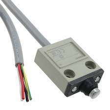
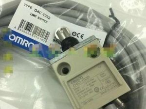
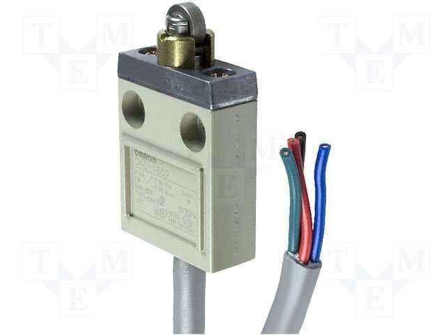
D4E-1C20N
Công tắc hành trình Omron
Slim and Compact Switch with Better Seal and Ensuring Longer Service Life than D4E
ast update: January 05, 2017
| Type | One-touch connector type |
Screw terminal type | |||||
|---|---|---|---|---|---|---|---|
| General- purpose |
Micro load | General- purpose without cable |
Micro load without cable |
General- purpose with cable |
Micro load with cable |
||
 |
 |
 |
 |
 |
 |
||
| Actuator | Model | Model | Model | Model | Model | Model | |
| Roller plunger |
 |
D4E-1A[]0N | D4E-2A10N | D4E-1A20N | D4E-2A20N | D4E-1A21N | D4E-2A21N |
| Crossroller plunger |
 |
D4E-1B[]0N | D4E-2B10N | D4E-1B20N | D4E-2B20N | D4E-1B21N | D4E-2B21N |
| Plunger |
 |
D4E-1C[]0N | D4E-2C[]0N | D4E-1C20N | D4E-2C20N | D4E-1C21N | D4E-2C21N |
| Sealed roller plunger |
 |
D4E-1D[]0N | D4E-2D10N | D4E-1D20N | D4E-2D20N | D4E-1D21N | D4E-2D21N |
| Sealed crossroller plunger |
 |
D4E-1E[]0N | — | D4E-1E20N | D4E-2E20N | D4E-1E21N | D4E-2E21N |
| Sealed plunger |
 |
D4E-1F[]0N | D4E-2F10N | D4E-1F20N | D4E-2F20N | D4E-1F21N | D4E-2F21N |
| Roller lever |
 |
D4E-1G[]0N | D4E-2G10N | D4E-1G20N | D4E-2G20N | D4E-1G21N | D4E-2G21N |
| One-way action roller lever |
 |
D4E-1H00N | — | D4E-1H20N | D4E-2H20N | D4E-1H21N | — |
Note: 1. When ordering, specify the current type by replacing the blank box of the model number with 0 for AC connector
or 1 for DC connector.
2. For the plunger and lever actuator models, the NC and NO terminal indicators are reversed.
3. Models are also available with molded terminals and with molded terminals and operation indicators. Refer to
Catalog.
Plug
For models with connectors, select one of the specified Cables with Connectors (sockets) from the following table.
| Applicable limit switches | Current Type | Type | No. of conductors | Cable length | Model |
|---|---|---|---|---|---|
| D4E-[][]00N | AC | Straight
![d4e-[]n_lineup2_1](https://www.omron.com.vn/Images/d4e-%5B%5Dn_lineup2_127-152667.gif "d4e-[]n_lineup2_1") |
4 | 2 m | XS2F-A421-D90-F |
| 5 m | XS2F-A421-G90-F | ||||
| D4E-[][]10N | DC | 2 m | XS2F-D421-D80-F | ||
| 5 m | XS2F-D421-G80-F |
Ratings
| Rated voltage | Standard load | Micro load | ||||||||
|---|---|---|---|---|---|---|---|---|---|---|
| Non-inductive load (A) | Inductive load (A) | Non-inductive load (A) | ||||||||
| Resistive load | Lamp load | Inductive load | Motor load | Resistive load | ||||||
| NC | NO | NC | NO | NC | NO | NC | NO | NC | NO | |
| 125 VAC 250 VAC |
5 (1) 5 (1) |
1.5 (1) 1.5 (1) |
3 (1) 3 (1) |
2 (1) 1 |
1 (1) 0.5 |
0.1 — |
||||
| 8 VDC 14 VDC 30 VDC 125 VDC 250 VDC |
5 (1) 5 (1) 5 (1) 0.5 0.25 |
— — — — — |
1.5 (1) 1.5 (1) 1.5 (1) 0.05 0.03 |
— — — — — |
0.1 0.1 0.1 — — |
|||||
| Minimum applicable load | Standard load | Micro load |
|---|---|---|
| 160 mA at 5 VDC | 1 mA at 5 VDC |
| Inrush current | NC | 10 A max. |
|---|---|---|
| NO | 10 A max. |
Note: 1. The above current ratings are for a standard current and the values in parentheses are for models with a
connector.
2. Inductive loads have a power factor of 0.4 min. (AC) and a time constant of 7 ms max. (DC).
3. Lamp load has an inrush current of 10 times the steady-state current.
4. Motor load has an inrush current of 6 times the steady-state current.
Characteristics
| Degree of protection | IP67 | |
|---|---|---|
| Durability * | Mechanical | 10,000,000 operations min. |
| Electrical | 500,000 operations min. (5 A at 250 VAC, resistive load) 5,000,000 operations min. (10 mA at 24 VDC, resistive load) |
|
| Operating speed | 0.1 mm/sec to 0.5 m/sec | |
| Operating frequency | Mechanical: 120 operations/min Electrical: 30 operations/min |
|
| Rated frequency | 50/60 Hz | |
| Insulation resistance | 100 MΩ min. (at 500 VDC) | |
| Contact resistance | 15 mΩ max. (initial value for the built-in switch when tested alone) | |
| Dielectric strength | Between terminals of same polarity |
1,000 VAC, 50/60 Hz for 1 min |
| Between each terminal and non-current-carrying metal part |
1,500 VAC, 50/60 Hz for 1 min/Uimp at 2.5 kV (EN60947-5-1) | |
| Rated insulation voltage (Ui) | 250V | |
| Pollution degree (operating environment) | 3 (EN60947-5-1) | |
| Short-circuit protective device (SCPD) | 10 A fuse (type gG or gI, IEC60269 approved) | |
| Conditional short-circuit current | 100 A (EN60947-5-1) | |
| Conventional enclosed thermal current (Ithe) | 5 A (EN60947-5-1) | |
| Protection against electric shock | Class II (grounding not required with double insulation) | |
| Vibration resistance | Malfunction | 10 to 55 Hz, 1.5-mm double amplitude |
| Shock resistance | Destruction | 1,000 m/s2 max. |
| Malfunction | 300 m/s2 max. | |
| Ambient operating temperature | -10°C to +80°C (with no icing) | |
| Ambient operating humidity | 35% to 95%RH | |
| Weight | Approx. 86 g (in case of roller plunger) | |
Note: 1. The above values are initial values.
2. The above ratings may vary depending on the model. Contact your OMRON representative for further details.
* Durability values are calculated at an operating temperature of +5°C to +35°C, and an operating humidity of 40% to
70%RH.


Reviews
There are no reviews yet.